找回密码
 立即注册
查看: 876|回复: 5

关于IO口输入电流问题

[复制链接]
  • 打卡等级:初来乍到
  • 打卡总天数:1
  • 最近打卡:2024-12-11 14:34:45

4

主题

9

回帖

64

积分

注册会员

积分
64
发表于 2023-7-12 10:10:13 | 显示全部楼层 |阅读模式
在使用STC8G1K08单片机过程中,遇到一些问题,特来请教各位老师
先放上电路连接图
2a85b060a5382626e87ac9785d5400c.jpg

程序中P33口模式是准双向口,并将P33 = 0(后面不会改变此IO口的状态);使用外部中断检测IO电平变化,中断触发为上升沿和下降沿都中断。
当开关闭合时,MOS管导通,会产生一个上升沿,但是此时的电流达到46mA
查看IO口内部结构时,当我给IO输入0时,红线经过的MOS管G极就为1,MOS管导通,电流经过MOS管到GND,由于我P33引脚上没有接电阻,5V经过外部的P沟道MOS管直接进入P33口,随后通过红线的路径到GND,此时是不是可以理解为5V和GND短路了呢?如果是短路,为什么电流只有46mA?46mA是不是已经超过单片机IO所能耐受的最大电流了?
关于IO口输入电流问题-1.png


回复

使用道具 举报 送花

  • 打卡等级:初来乍到
  • 打卡总天数:1
  • 最近打卡:2024-12-11 14:34:45

4

主题

9

回帖

64

积分

注册会员

积分
64
发表于 2023-7-12 10:13:55 | 显示全部楼层
电路没有其它负载产生电流
回复 支持 反对

使用道具 举报 送花

  • 打卡等级:以坛为家I
  • 打卡总天数:328
  • 最近打卡:2025-03-09 19:40:01

9

主题

328

回帖

4501

积分

荣誉版主

积分
4501
发表于 2023-7-12 10:49:27 | 显示全部楼层


该电路是短路状态,但IO灌电流典型值只有20mA
Screenshot 2023-07-12 104532.png

Screenshot 2023-07-12 104610.png

回复 支持 反对

使用道具 举报 送花

  • 打卡等级:初来乍到
  • 打卡总天数:1
  • 最近打卡:2024-12-11 14:34:45

4

主题

9

回帖

64

积分

注册会员

积分
64
发表于 2023-7-12 11:27:41 | 显示全部楼层
kk*** 发表于 2023-7-12 10:49
该电路是短路状态,但IO灌电流典型值只有20mA

是不是我让P33=0的时候,IO口内部的MOS管导通了,然后我外部的MOS管导通之后,5V直接经过IO口进入内部MOS管那里到GND,形成短路了?
回复 支持 反对

使用道具 举报 送花

  • 打卡等级:初来乍到
  • 打卡总天数:4
  • 最近打卡:2025-05-01 06:58:22

5

主题

184

回帖

1333

积分

金牌会员

积分
1333
发表于 2023-7-13 08:01:15 | 显示全部楼层
本帖最后由 jmg 于 2023-7-13 14:11 编辑
When the switch is closed, the MOS tube is turned on, and a rising edge will be generated, but the current at this time reaches 46mA.
If it is a short circuit, why  is the current only 46mA?  Has 46mA exceeded the maximum current that the microcontroller IO can stand?

You are correct to think 46mA is excessive, normally such a circuit is avoided as 46mA is too high for simple button sense.
You do not want to fight the LOW driving N-FET.
The reason you measure ~46mA is seen on these CMOS curves (from toshiba data, but applicable to all CMOS parts )
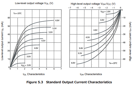

1.png

The 8051 port is designed with light pullups, so if you want to sense a switch to GND as your circuit shows, just omit the diode, and PFET and connect switch directly to P33 (you can use a 1k series resistor for ESD protection, if it is a remote switch)
P33 will then read HI for open switch and LO for closed switch.
As above, the peak curent needed through the switch is ~270uA at Vin ~ 2.0V, and drops to < 50uA at Vin = 0V
There is an optional 4.1k resistor pullup via P3PU, which can increase the switch current to ~ 1.2mA
回复 支持 反对

使用道具 举报 送花

  • 打卡等级:初来乍到
  • 打卡总天数:1
  • 最近打卡:2024-12-11 14:34:45

4

主题

9

回帖

64

积分

注册会员

积分
64
发表于 2023-7-13 22:01:16 | 显示全部楼层
jm*** 发表于 2023-7-13 08:01
You are correct to think 46mA is excessive, normally such a circuit is avoided as 46mA is too high  ...

Thank you! The problem has been resolved.I connected a resistor in series at P3.3 and configured this port as a high impedence input.interruption can detect edge changes.
回复 支持 反对

使用道具 举报 送花

您需要登录后才可以回帖 登录 | 立即注册

本版积分规则

QQ|手机版|小黑屋|深圳国芯人工智能有限公司 ( 粤ICP备2022108929号-2 )

GMT+8, 2025-5-2 20:39 , Processed in 0.123010 second(s), 80 queries .

Powered by Discuz! X3.5

© 2001-2025 Discuz! Team.

快速回复 返回顶部 返回列表